bold.daemon
Table of Contents
Reticulum Information
Reticulum is a network building stack that uses encryption by default. It targets inexpensive radio hardware and is capable of running on most OSs.
My node info
| Name | Address | Modes |
|---|---|---|
| suah | 3b5bc6888356193f1ac1bfb716c1beef | pages (has a copy of the build tips below) |
| qbit-web | 8b96aadcf59432afec00bdde6edc1e60 | chat |
| qbit@europa | 745a11b819e01a722cd59ddf74c4b2bf | chat |
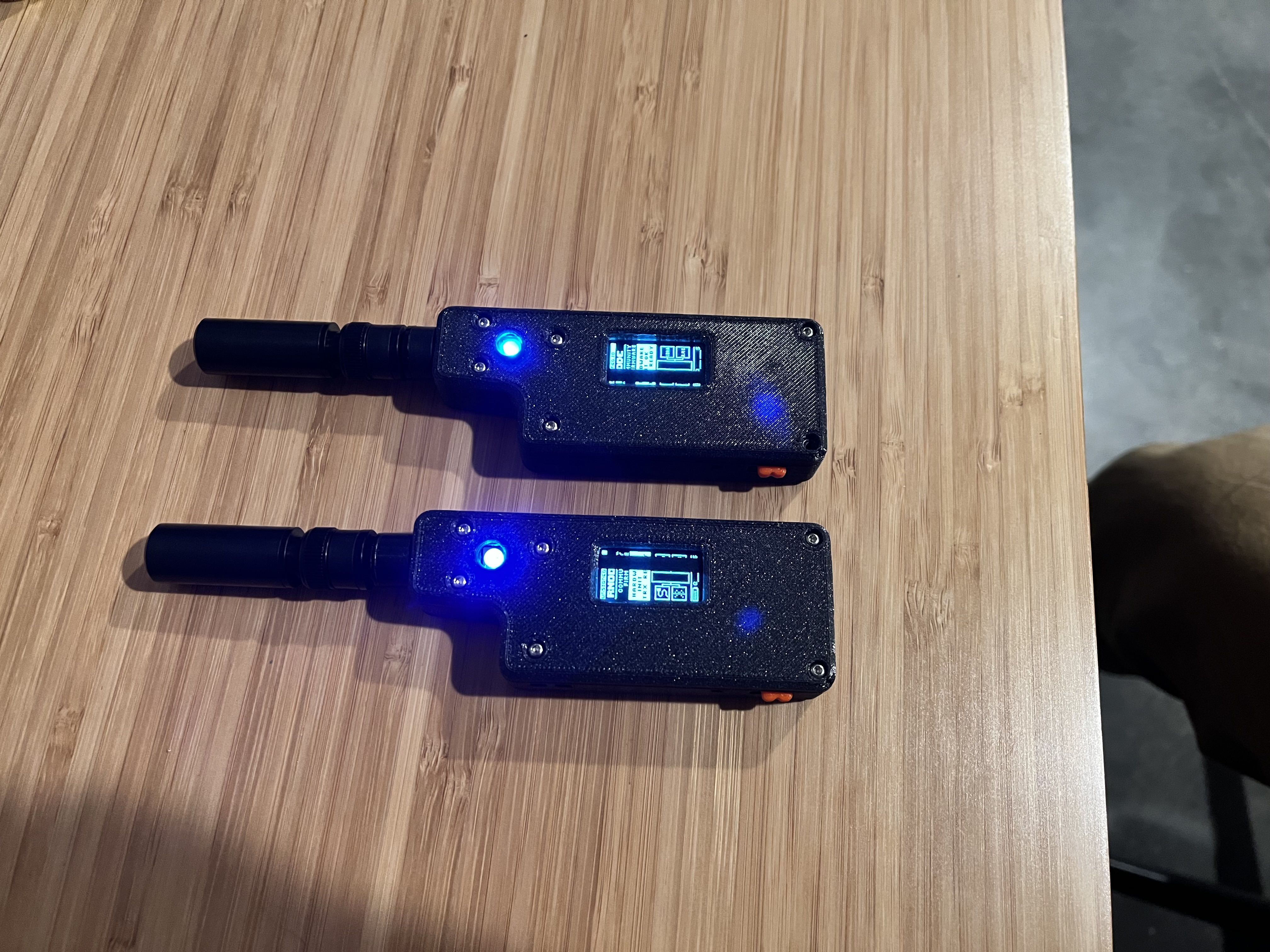
RNode Build Tips
After building two RNodes, I have a few tips and tricks for anyone wanting to make their own.
It's not exactly easy and having a few specialty tools helps a lot!
Tools used:
- Hakko FX-888D Soldering Iron
- Hot air station (Sparkfun 303D)
- Angled, flat faced clippers (CHP-170 Micro Cutter)
- Box cutter with fresh blade (or at least intact tip)
- Framework Laptop screwdriver (for the pry bar)
LORA32
Removing the SMA connector
Clip the ends of the soldered side of the SMA connector. Next apply copious amounts of heat until it falls out.
I used a hot air station on 480F / medium air flow. It took about a minute or two before the connector was loose enough to pull off with pliers.
Removing the LCD backing
For this step, slow and steady is the way.
Start by gently prying between the plastic and the PCB. You can use something like a screwdriver for this step.
Once you have the plastic part popped up, get a thin plastic pry tool.
Grab both ends of the plastic and gently push against the back (push towards the back of the LCD). It should flex enough for an edge of the LCD to dislodge.
Next GENTLY slide your pry tool between the LCD and the plastic.
Slowly work the pry tool in until you can pull the LCD fully off the plastic.
Switching between SMA and µ.FL
Using your soldering tip, gently push against the jumper until it pops off.
Next take a thin piece of wire and put a 90° bend at the end. The wire after the angle should just fit between the pads on the µ.FL connector.
Next use your soldering iron to solder the small wire to the pads. Clip the remaining lengths of wire so they don't short something out.
Case
Fitting the LCD
Do not force this. It's very easy to break the glass!
Depending on your printer.. you might not need this step but for me the clearance was a bit too tight.
Using a razor blade, slide across the case's screen holder's long edges. Scrape a few times, then check the fit. Rinse. Repeat.
When fitting, make note of where the LCD seems to hang. Focus your scrapes there. Be extra aware of the corners!
Cable Routing
The DATA cable for the LCD is much easier to route if you bring it back up to the "top" of the LORA32. I opted to route it via the hole next to the RST switch. From there, route it back towards pin 12.
Fitting the parts together
- Slot the LCD in first.
- Make sure the antenna is in the other half of the case (putting the nut on at this point can help prevent the antenna from falling out while futzing with things).
- Put the printed power switch into the case.
- Slide the power switch into the printed power switch (you will likely have to move it around a bit).
- Using a thin object, ensure the cables are all in their routing slots. Keep squeezing the halves of the case together while doing this.
- Once you have an area that fits (the plastic parts touch each other), put a screw in to hold it in place.
- Work around the case until all the cables and screws are in place.
About
Mostly a dumping ground for various things I find interesting.
Byte-sized mischief maker
Cron jobs whispered in darkness
System's secret friend
– Someone else's computer